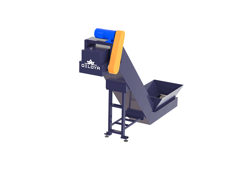
Conveying short metal chips between processing stages
The DILOYA Steel Hinged Belt Conveyor is a material-handling accessory for suitable short metal machining chips. It transfers chips from a collection or receiving point to downstream equipment, reducing the need to move the same material repeatedly by hand or container.
The steel chain-plate conveying design can be configured around an inclined transfer route and a required discharge height. The receiving arrangement, conveyor length, conveying width and installation angle are selected for the actual chips, loading method and plant layout.
Parameter:
| Model | STC200 | STC300 | STC400 | STC500 | STC800 |
| Power | 0.2kw | 0.4kw | 0.4kw | 0.75kw | 1.5kw |
| Width | 200mm | 300mm | 400mm | 500mm | 800mm |
| Height | 1200mm | 1200mm | 1500mm | 1800mm | 2100mm |
| Machine Weight | 320kg | 430kg | 560kg | 890kg | 1160kg |
Suitable metal-chip applications
Typical feedstocks include suitable short steel and iron chips, aluminium chips, copper chips and other prepared machining swarf. Selection depends on chip geometry, bulk density, fluid condition and the amount of material to be moved.
Long, tangled turnings may not behave like free-flowing short chips and require a separate assessment or upstream size reduction. Bars, tools, heavy solid offcuts and other unsuitable contaminants must be excluded from a conveyor selected for machining chips.
Steel chain-plate conveying design
The moving steel conveying surface carries the chips along the selected route towards the discharge. The drive and chain-plate arrangement are matched to the required loading and transfer duty. A receiving hopper or inlet arrangement directs material onto the conveyor, while the outlet is positioned above or beside the next collection or processing point.
Inclined conveying allows the system to bridge a height difference between equipment. The permitted angle and reliable loading condition depend on chip behaviour, the conveying arrangement and the selected machine design; they should not be assumed to be the same for every material.
Typical operating sequence
1> Receive the chips: collect suitable short chips from a machine, bin or upstream process.
2> Load consistently: introduce material at a rate matched to conveyor capacity and downstream demand.
3> Transfer and elevate: the steel chain-plate surface moves the chips along the configured route.
4> Discharge into the next stage: deliver to a collection container, buffer hopper or compatible processing inlet.
Integration with a metal-chip processing line
The conveyor can form a handling link between chip collection, material preparation, centrifugal drying, buffering and briquetting. The precise connection depends on the line: it is not necessary for every project to include all of these processes.
Engineering coordination covers the receiving height, loading position, discharge height, outlet direction, conveyor capacity and interface with the receiving hopper or machine. Appropriate controls can be specified to coordinate transfer with the connected equipment.
The conveying rate must be selected together with the sustained output of upstream equipment and the receiving capacity of the next stage. A conveyor is a transfer device, not an unlimited buffer. Where a working material reserve is needed, provide a separately sized buffer arrangement.
Practical handling benefits
> Connected material flow: move suitable short chips between collection and processing points.
> Height transfer: use an inclined arrangement where the downstream inlet is elevated.
> Reduced repeated handling: limit intermediate container movements where a connected layout is practical.
> Layout-specific configuration: match the conveyor length, width and discharge to the installation.
> Line coordination: select transfer capacity around actual production demand.
Fluid condition and housekeeping
Metal chips may carry cutting oil, coolant or water. The conveyor and surrounding collection arrangements must account for that condition so liquid does not create uncontrolled leakage or housekeeping problems. Dedicated fluid collection, drainage or separation features are evaluated and specified where required; the conveyor alone should not be described as a dryer or de-oiling machine.
If a defined residual-fluid target is required, assess an appropriate separation stage in addition to conveying. Recovered fluid must be managed according to its condition and the receiving process.
Operation and maintenance
Avoid overloading the receiving area or allowing material to build up at the discharge. Follow the selected model's inspection and maintenance requirements for the conveying surface, chain, drive and guarding.
Stop and isolate the equipment before clearing obstructions, inspection or maintenance. Keep personnel clear of moving components and transfer points, and use the protective arrangements specified for the installation.
Information needed for selection
Send photos or samples of the chips, metal type, typical chip dimensions, bulk density, fluid condition and required transfer rate. Provide the receiving and discharge heights, preferred layout, loading method, connected equipment, available floor space and local power supply.
DILOYA will evaluate a suitable steel hinged belt conveyor around the material and site requirements. Final dimensions, inclination, drive configuration and conveying capacity are confirmed for the selected duty rather than assumed from appearance alone.